Last Updated on May 3, 2018 by
-
Recommend
Packet Tracer – Configuring Extended ACLs – Scenario 2 (Answer Version)
Answer Note: Red font color or Gray highlights indicate text that appears in the Answer copy only.
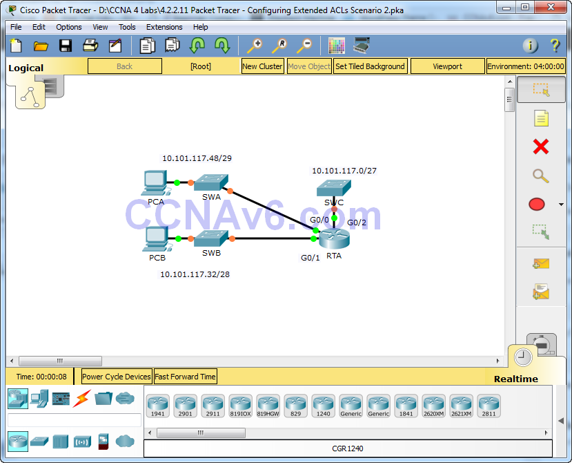
Topology

4.2.2.11 Packet Tracer – Configuring Extended ACLs Scenario 2
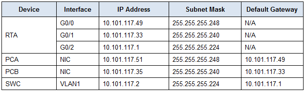
Addressing Table
| Device | Interface | IP Address | Subnet Mask | Default Gateway |
| RTA | G0/0 | 10.101.117.49 | 255.255.255.248 | N/A |
| G0/1 | 10.101.117.33 | 255.255.255.240 | N/A | |
| G0/2 | 10.101.117.1 | 255.255.255.224 | N/A | |
| PCA | NIC | 10.101.117.51 | 255.255.255.248 | 10.101.117.49 |
| PCB | NIC | 10.101.117.35 | 255.255.255.240 | 10.101.117.33 |
| SWC | VLAN1 | 10.101.117.2 | 255.255.255.224 | 10.101.117.1 |
Objectives
Part 1: Configure, Apply and Verify an Extended Numbered ACL
Part 2: Reflection Questions
Background / Scenario
In this scenario, devices on one LAN are allowed to remotely access devices in another LAN using the Telnet protocol. Besides ICMP, all traffic from other networks is denied.
Part 1: Configure, Apply and Verify an Extended Numbered ACL
Configure, apply and verify an ACL to satisfy the following policy:
- Telnet traffic from devices on the 10.101.117.32/28 network is allowed to devices on the 10.101.117.0/27 networks.
- ICMP traffic is allowed from any source to any destination
- All other traffic to 10.101.117.0/27 is blocked.
Step 1: Configure the extended ACL.
- From the appropriate configuration mode on RTA, use the last valid extended access list number to configure the ACL. Use the following steps to construct the first ACL statement:
- The last extended list number is 199.
- The protocol is TCP.
- The source network is 10.101.117.32.
- The wildcard can be determined by subtracting 255.255.255.240 from 255.255.255.255.
- The destination network is 10.101.117.0.
- The wildcard can be determined by subtracting 255.255.255.224 from 255.255.255.255.
- The protocol is Telnet.
- What is the first ACL statement?
- access-list 199 permit tcp 10.101.117.32 0.0.0.15 10.101.117.0 0.0.0.31 eq telnet.
- ICMP is allowed, and a second ACL statement is needed. Use the same access list number to permit all ICMP traffic, regardless of the source or destination address. What is the second ACL statement? (Hint: Use the any keywords)
- access-list 199 permit icmp any any
- All other IP traffic is denied, by default.
Step 2: Apply the extended ACL.
The general rule is to place extended ACLs close to the source. However, since access list 199 affects traffic originating from both networks 10.101.117.48/29 and 10.101.117.32/28, the best placement for this ACL might be on interface Gigabit Ethernet 0/2 in the outbound direction. What is the command to apply ACL 199 to the Gigabit Ethernet 0/2 interface?
ip access-group 199 out
Step 3: Verify the extended ACL implementation.
- Ping from PCB to all of the other IP addresses in the network. If the pings are unsuccessful, verify the IP addresses before continuing.
- Telnet from PCB to SWC. The password is cisco.
- Exit the Telnet service of the SWC.
- Ping from PCA to all of the other IP addresses in the network. If the pings are unsuccessful, verify the IP addresses before continuing.
- Telnet from PCA to SWC. The access list causes the router to reject the connection.
- Telnet from PCA to SWB. The access list is placed on G0/2 and does not affect this connection.
- After logging into SWB, do not log out. Telnet to SWC.
Part 2: Reflection Questions
- How was PCA able to bypass access list 199 and Telnet to SWC? Two steps were used: First, PCA used Telnet to access SWB. From SWB, Telnet was allowed to SWC.
- What could have been done to prevent PCA from accessing SWC indirectly, while allowing PCB Telnet access to SWC? Access list 199 should have been written to deny Telnet traffic from the 10.101.117.48 /29 network while permitting ICMP. It should have been placed on G0/0 of RTA.
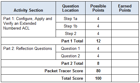
Suggested Scoring Rubric
| Activity Section | Question Location | Possible Points | Earned Points |
| Part 1: Configure, Apply and Verify an Extended Numbered ACL | Step 1a | 4 | |
| Step 1b | 4 | ||
| Step 2 | 4 | ||
| Part 1 Total | 12 | ||
| Part 2: Reflection Questions | Question 1 | 4 | |
| Question 2 | 4 | ||
| Part 2 Total | 8 | ||
| Packet Tracer Score | 80 | ||
| Total Score | 100 |
-
Recommend

Last Updated on April 28, 2018 by InfraExam
Packet Tracer – Configuring Extended ACLs – Scenario 2 (Answer Version)
Answer Note: Red font color or Gray highlights indicate text that appears in the Answer copy only.
Topology
Addressing Table
| Device | Interface | IP Address | Subnet Mask | Default Gateway |
| RTA | G0/0 | 10.101.117.49 | 255.255.255.248 | N/A |
| G0/1 | 10.101.117.33 | 255.255.255.240 | N/A | |
| G0/2 | 10.101.117.1 | 255.255.255.224 | N/A | |
| PCA | NIC | 10.101.117.51 | 255.255.255.248 | 10.101.117.49 |
| PCB | NIC | 10.101.117.35 | 255.255.255.240 | 10.101.117.33 |
| SWC | VLAN1 | 10.101.117.2 | 255.255.255.224 | 10.101.117.1 |
Objectives
Part 1: Configure, Apply and Verify an Extended Numbered ACL
Part 2: Reflection Questions
Background / Scenario
In this scenario, devices on one LAN are allowed to remotely access devices in another LAN using the Telnet protocol. Besides ICMP, all traffic from other networks is denied.
Part 1: Configure, Apply and Verify an Extended Numbered ACL
Configure, apply and verify an ACL to satisfy the following policy:
- Telnet traffic from devices on the 10.101.117.32/28 network is allowed to devices on the 10.101.117.0/27 networks.
- ICMP traffic is allowed from any source to any destination
- All other traffic to 10.101.117.0/27 is blocked.
Step 1: Configure the extended ACL.
- From the appropriate configuration mode on RTA, use the last valid extended access list number to configure the ACL. Use the following steps to construct the first ACL statement:
- The last extended list number is 199.
- The protocol is TCP.
- The source network is 10.101.117.32.
- The wildcard can be determined by subtracting 255.255.255.240 from 255.255.255.255.
- The destination network is 10.101.117.0.
- The wildcard can be determined by subtracting 255.255.255.224 from 255.255.255.255.
- The protocol is Telnet.
- What is the first ACL statement?
- access-list 199 permit tcp 10.101.117.32 0.0.0.15 10.101.117.0 0.0.0.31 eq telnet.
- ICMP is allowed, and a second ACL statement is needed. Use the same access list number to permit all ICMP traffic, regardless of the source or destination address. What is the second ACL statement? (Hint: Use the any keywords)
- access-list 199 permit icmp any any
- All other IP traffic is denied, by default.
Step 2: Apply the extended ACL.
The general rule is to place extended ACLs close to the source. However, since access list 199 affects traffic originating from both networks 10.101.117.48/29 and 10.101.117.32/28, the best placement for this ACL might be on interface Gigabit Ethernet 0/2 in the outbound direction. What is the command to apply ACL 199 to the Gigabit Ethernet 0/2 interface?
ip access-group 199 out
Step 3: Verify the extended ACL implementation.
- Ping from PCB to all of the other IP addresses in the network. If the pings are unsuccessful, verify the IP addresses before continuing.
- Telnet from PCB to SWC. The password is cisco.
- Exit the Telnet service of the SWC.
- Ping from PCA to all of the other IP addresses in the network. If the pings are unsuccessful, verify the IP addresses before continuing.
- Telnet from PCA to SWC. The access list causes the router to reject the connection.
- Telnet from PCA to SWB. The access list is placed on G0/2 and does not affect this connection.
- After logging into SWB, do not log out. Telnet to SWC.
Part 2: Reflection Questions
- How was PCA able to bypass access list 199 and Telnet to SWC? Two steps were used: First, PCA used Telnet to access SWB. From SWB, Telnet was allowed to SWC.
- What could have been done to prevent PCA from accessing SWC indirectly, while allowing PCB Telnet access to SWC? Access list 199 should have been written to deny Telnet traffic from the 10.101.117.48 /29 network while permitting ICMP. It should have been placed on G0/0 of RTA.
Suggested Scoring Rubric
| Activity Section | Question Location | Possible Points | Earned Points |
| Part 1: Configure, Apply and Verify an Extended Numbered ACL | Step 1a | 4 | |
| Step 1b | 4 | ||
| Step 2 | 4 | ||
| Part 1 Total | 12 | ||
| Part 2: Reflection Questions | Question 1 | 4 | |
| Question 2 | 4 | ||
| Part 2 Total | 8 | ||
| Packet Tracer Score | 80 | ||
| Total Score | 100 |
Packet Tracer – Configuring Extended ACLs – Scenario 2 (Instructor Version)
Instructor Note: Red font color or Gray highlights indicate text that appears in the instructor copy only.
Topology
Addressing Table
Objectives
Part 1: Configure, Apply and Verify an Extended Numbered ACL
Part 2: Reflection Questions
Background / Scenario
In this scenario, devices on one LAN are allowed to remotely access devices in another LAN using the Telnet protocol. Besides ICMP, all traffic from other networks is denied.
Part 1: Configure, Apply and Verify an Extended Numbered ACL
Configure, apply and verify an ACL to satisfy the following policy:
Telnet traffic from devices on the 10.101.117.32/28 network is allowed to devices on the 10.101.117.0/27 networks.
ICMP traffic is allowed from any source to any destination
All other traffic to 10.101.117.0/27 is blocked.
Step 1: Configure the extended ACL.
a. From the appropriate configuration mode on RTA, use the last valid extended access list number to configure the ACL. Use the following steps to construct the first ACL statement:
1) The last extended list number is 199.
2) The protocol is TCP.
3) The source network is 10.101.117.32.
4) The wildcard can be determined by subtracting 255.255.255.240 from 255.255.255.255.
5) The destination network is 10.101.117.0.
6) The wildcard can be determined by subtracting 255.255.255.224 from 255.255.255.255.
7) The protocol is Telnet.
What is the first ACL statement?
access-list 199 permit tcp 10.101.117.32 0.0.0.15 10.101.117.0 0.0.0.31 eq telnet.
b. ICMP is allowed, and a second ACL statement is needed. Use the same access list number to permit all ICMP traffic, regardless of the source or destination address. What is the second ACL statement? (Hint: Use the any keywords)
access-list 199 permit icmp any any
c. All other IP traffic is denied, by default.
Step 2: Apply the extended ACL.
The general rule is to place extended ACLs close to the source. However, since access list 199 affects traffic originating from both networks 10.101.117.48/29 and 10.101.117.32/28, the best placement for this ACL might be on interface Gigabit Ethernet 0/2 in the outbound direction. What is the command to apply ACL 199 to the Gigabit Ethernet 0/2 interface?
ip access-group 199 out
Step 3: Verify the extended ACL implementation.
a. Ping from PCB to all of the other IP addresses in the network. If the pings are unsuccessful, verify the IP addresses before continuing.
b. Telnet from PCB to SWC. The password is cisco.
c. Exit the Telnet service of the SWC.
d. Ping from PCA to all of the other IP addresses in the network. If the pings are unsuccessful, verify the IP addresses before continuing.
e. Telnet from PCA to SWC. The access list causes the router to reject the connection.
f. Telnet from PCA to SWB. The access list is placed on G0/2 and does not affect this connection.
g. After logging into SWB, do not log out. Telnet to SWC.
Part 2: Reflection Questions
a. How was PCA able to bypass access list 199 and Telnet to SWC?
Two steps were used: First, PCA used Telnet to access SWB. From SWB, Telnet was allowed to SWC.
b. What could have been done to prevent PCA from accessing SWC indirectly, while allowing PCB Telnet access to SWC?
Access list 199 should have been written to deny Telnet traffic from the 10.101.117.48 /29 network while permitting ICMP. It should have been placed on G0/0 of RTA.
Suggested Scoring Rubric
[sociallocker id=”54558″]
[/sociallocker]
В этом сценарии
устройствам в одной сети LAN
разрешается удалённый доступ к устройствам
другой LAN
через протокол Telnet.
За исключением ICMP,
весь трафик от других сетей запрещён.
Схема сети представлена на рисунке 33.

Рисунок 33 – Схема
сети
Настраиваем
расширенный нумерованный ACL-список
следующими командами:
accesslist
199 permittcp
10.101.117.32 0.0.0.15 10.101.117.0 0.0.0.31 eqtelnet–
трафик по протоколу Telnet
в сети 10.101.117.32/28 разрешён для передачи
на устройства в сетях 10.100.117.0/27.
access-list
199 permiticmpanyany
– трафик ICMP
разрешён от любого устройства и в любом
направлении.
Остальной трафик
запрещён по умолчанию.
interface
gigabitethernet0/2
ipaccess-group
199 out
– размещениесписканаинтерфейсе.
Для проверки работы
расширенного списка сначала необходимо
отправить эхо-запросыот компьютера PCB
на все остальные IP-адреса в сети (рисунок
34). Далее отправляютсяэхо-запросы от
компьютера PCA
на все остальные IP-адреса
в сети (рисунок 35).

Рисунок 34–Эхо-запрос
от РСВ

Рисунок 35 –
Эхо-запрос от РСА
6 Настройка расширенных acl-списков. Сценарий 3
В этом сценарии
конкретным устройствам сети LAN разрешается
доступ к нескольким службам серверов,
размещённых в сети Интернет. Используемая
сеть представлена на рисунке 36.

Рисунок 36 – Схема
сети
Необходимо
использовать один именованный ACL-список
для реализации следующих правил:
1 Запретить доступ
через протоколы HTTP и HTTPS с PC1 на серверы
Server1 и Server2. Эти серверы находятся внутри
облака, известны только их IP-адреса.
2Заблокировать
FTP-доступ с PC2 к серверам Server1 и Server2.
3Заблокировать
ICMP-доступ с PC3 к серверам Server1 и Server2.
Настройка
расширенного именованного ACL-списка
осуществлялась следующими командами:
ip
access-list extended ACL
– создаемсписок.
denytcphost
172.31.1.101 host
64.101.255.254 eqwww–
правило, запрещающее доступ с PC1
к серверу Server1,
только для HTTP.
denytcphost
172.31.1.101 host
64.101.255.254 eq
443 – правило,
запрещающее доступ с PC1
к серверу Server1,
только для HTTPS.
denytcphost
172.31.1.101 host
64.103.255.254 eqwww–
правило, запрещающее доступ с PC1
к серверу Server2,
только для HTTP.
denytcphost
172.31.1.101 host
64.103.255.254 eq
443 – правило,
запрещающее доступ с PC1
к серверу Server2,
только для HTTPS.
denytcphost
172.31.1.102 host
64.101.255.254 eqftp–
правило, запрещающее доступ с PC2
к серверу Server1,
только для FTP.
denytcphost
172.31.1.102 host
64.103.255.254 eqftp
– правило, запрещающее доступ с PC2
к серверу Server2,
только для FTP.
denyicmphost
172.31.1.103 host
64.101.255.254 –
правило, запрещающее ICMP-доступ
с PC3
к серверу Server1.
denyicmphost
172.31.1.103 host
64.103.255.254 –
правило, запрещающее ICMP-доступ
с PC3
к серверу Server2.
permitipanyany
– разрешение остальногоIP-трафика.
interfacegigabitEthernet
0/0
ipaccess-groupACLin
– применениеACL-списка
на соответствующем интерфейсе и
направлении.
Проверка расширенного
ACL-списка заключается в следующем:
проверяется доступ к веб-сайтам на
серверах Server1 и Server2, используя веб-браузер
PC1, а также протоколы HTTP и HTTPS (рисунок
6.2), проверяется FTP-доступ к серверам
Server1 и Server2 с компьютера PC1 (рисунок
6.3),выполняются эхо-запросы на серверы
Server1 и Server2 от PC1 (рисунок 6.4). Аналогично
поверяются РС2 и РС3. Удачный доступ к
веб-сайтам на серверах от РС2 и РС3 – на
рисунке 6.5. Неудачный FTP-доступ к серверам
от РС2 – на рисунке 6.6. Неудачные
эхо-запросы от РС3 к серверам представлены
на рисунке 6.7.


Рисунок 6.2 –
Проверка доступа через HTTP и HTTPS

Рисунок 6.3 —
FTP-доступ к серверам Server1 и Server2 с PC1

Рисунок 6.4 —
Эхо-запросы на серверы Server1 и Server2 от PC1

Рисунок 6.5 — Удачный
доступ к веб-сайтам на серверах от РС2
и РС3

Рисунок 6.6 — Неудачный
FTP-доступ к серверам от РС2

Рисунок 6.7 — Неудачные
эхо-запросы от РС3 к серверам
Таблица распределения адресов
оборудование
интерфейс
айпи адрес
Маска подсети
Шлюз по умолчанию
RTA
G0/0
10.101.117.49
255.255.255.248
не применимо
G0/1
10.101.117.33
255.255.255.240
не применимо
G0/2
10.101.117.1
255.255.255.224
не применимо
PCA
NIC
10.101.117.51
255.255.255.248
10.101.117.49
PCB
NIC
10.101.117.35
255.255.255.240
10.101.117.33
SWC
VLAN1
10.101.117.2
255.255.255.224
10.101.117.1
цель
Часть 1. Настройка, применение и проверка ACL с расширенным номером
Часть 2: вопросы для размышления
Фон / сцена
В этом сценарии система позволяет устройствам в одной локальной сети получать удаленный доступ к устройствам в другой локальной сети с помощью протокола Telnet. За исключением ICMP, весь трафик из других сетей будет отклонен.
Часть 1. Настройка, применение и проверка расширенного номера ACL
Настраивать, применять и проверять списки управления доступом, чтобы обеспечить соответствие следующим политикам:
· Разрешить трафик Telnet, генерируемый устройствами в сети 10.101.117.32/28, входить в устройства в сети 10.101.117.0/27.
ICMP-трафик может достигать любого адреса назначения с любого адреса источника.
· Весь другой трафик, входящий в 10.101.117.0/27, будет заблокирован.
Шаг 1. Настройте расширенный ACL.
В соответствующем режиме конфигурации RTA используйте последний действительный номер расширенного списка доступа для настройки ACL. Выполните следующие действия, чтобы создать первую инструкцию ACL:
1) Последний номер расширенного списка — 199.
2) Протокол TCP.
3) Исходная сеть — 10.101.117.32.
4) Подстановочный знак можно определить путем вычитания 255.255.255.240 из 255.255.255.255.
5) Целевая сеть — 10.101.117.0.
6) Подстановочный знак можно определить путем вычитания 255.255.255.224 из 255.255.255.255.
7) Протокол — Telnet.
Какая была первая инструкция ACL?
б. Разрешен протокол ICMP, требуется второй оператор ACL. Использование одного и того же номера списка доступа разрешает весь трафик ICMP, независимо от адреса источника или назначения. Что такое второй оператор ACL? (Подсказка: используйте любое ключевое слово)
c. По умолчанию весь другой IP-трафик запрещен.
Шаг 2: Примените расширенный ACL.
В общем, размещайте расширенный ACL рядом с адресом источника. Однако, поскольку список доступа 199 будет влиять на трафик от 10.101.117.48/29 и 10.101.117.32/28, лучше всего разместить этот ACL на интерфейсе Gigabit Ethernet 0/2 в исходящем направлении. Какую команду я могу использовать для применения ACL 199 к интерфейсу Gigabit Ethernet 0/2?
Шаг 3: Проверьте реализацию расширенного ACL.
а. эхо-запрос для всех остальных IP-адресов в сети с платы. Если операция ping не удалась, проверьте IP-адрес перед продолжением.
б) Подключитесь к SWC через Telnet с печатной платы. Пароль — cisco.
в. Закройте службу Telnet SWC.
г. Выполните эхо-запрос всех остальных IP-адресов в сети от PCA. Если операция ping не удалась, проверьте IP-адрес перед продолжением.
д. Подключитесь к SWC с PCA через Telnet. Список доступа заставил маршрутизатор отказаться от подключения.
е. Подключитесь от PCA к SWB через Telnet. Список доступа находится на G0 / 2 и не влияет на это соединение.
g. После входа в SWB не выходите из системы. Подключитесь к SWC через Telnet.

Вот, чтобы следовать подсказкам, просто скопируйте и вставьте следующие команды
en
conf t
access-list 199 permit tcp 10.101.117.32 0.0.0.15 10.101.117.0 0.0.0.31 eq telnet
access-list 199 permit icmp any any
interface g0/2
ip access-group 199 out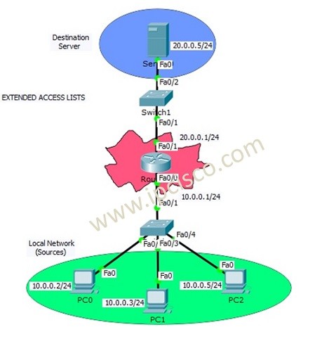
Packet Tracer Extended Access Lists Configuration
We have learned Access Control Lists overview and Standard ACL Configuration at the previous lessons. In this lesson we will focus on Cisco Extended ACL Configuration with Cisco Packet Tracer. We will use the below topology for our packet tracer configuration.
You can DOWNLOAD the Cisco Packet Tracer example with .pkt format at the End of This Lesson.
Like Standard ACL Configuration Example, we will use one router, one destination server and 3 PCS in common. The switches in the topology will onlu used for port need.
Extended ACLs are a little complex if we compare with Standard ACLs. With Extended ACLs, we can restrict or allow specific things like destination, protocol or port.
In this Cisco Extended ACL Configuration example, we will allow/deny ICMP protocol through the server. As you know, ICMP is ping protocol. Here, PC0 and PC1 will be allowed and PC2 will be denied.
You can also learn DHCP Server Configuration With Packet Tracer
Extended Access-List Configuration
Let’s start to configure router for our Cisco Extended ACL Configuration.
For Extended ACLs, we can use Extended Access-List Number range 100 to 199. Here, we will use 100.
Router # configure terminal
Router (config)# ip access-list extended 100
Router (config-ext-nacl)# permit icmp 10.0.0.0 0.0.0.3 host 20.0.0.5
Router (config-ext-nacl)# deny icmp host 10.0.0.5 host 20.0.0.5 host-unreachable
Router (config-ext-nacl)# end
Router # copy run start
You can also DOWNLOAD all the Packet Tracer examples with .pkt format in Packet Tracer Labs section.

Содержание
- 1 Что такое Access Control List?
- 2 Какие бывают ACL?
- 2.1 Стандартные списки ACL
- 2.2 Расширенные списки ACL
- 2.3 Синтаксис расширенных списков ACL.
- 2.4 Примеры расширенных ACL
- 2.4.1 Настраиваем роутер.
- 2.5 Приступим к настройке ACL-ов.
- 2.5.1 Запрещаем FTP трафик.
Пришло время поговорить об ACL подробней. Как взрослые люди, начнём делать серьёзные вещи. Да и я, наконец, собрался с мыслями и поковырял эту тему.
В данной статье мы рассмотрим простые типовые конфигурации для списков управления доступом на базе Cisco ACL, которые фильтруют IP-пакеты в зависимости от следующих данных:
- адрес источника (source address);
- адрес назначения (destination address);
- тип пакета (протокол верхнего уровня);
Маршрутизатор проверяет каждый пакет и на основании вышеперечисленных критериев, указанных в ACL определяет, что нужно сделать с пакетом, пропустить или отбросить.
Что такое Access Control List?
IP ACL – последовательный набор правил разрешающих или запрещающих прохождение пакета. Маршрутизатор последовательно проверяет каждый пакет на соответствие правилам. После первого же совпадения принимается решение и дальше правила не обрабатываются.
Если ни одно из правил не подошло, то пакет отбрасывается из-за неявного последнего правила deny all.
Можно выделить следующие виды списков контроля доступа:
- стандартные ACL;
- расширенные ACL (об этом речь пойдёт ниже);
- динамические ACL (ключ и замок);
- именованные IP-списки ACL;
- рефлексивные ACL;
- синхронизируемые списки ACL, использующие временные диапазоны;
- прокси-аутентификации;
- Turbo ACL;
- контекстно-ориентированные ACL;
- откомментированные записи IP ACL;
- распределённые синхронизируемые ACL;
Всему своё время, а мы рассмотрим самое распространённое – стандартные и расширенные списки контроля доступа.
Стандартные списки ACL
Формат синтаксиса команды стандартного ACL выглядит так:
# access-list number {permit|deny} {host|source source-wildcard|any}
- permit – пропускаем пакет.
- deny – отбрасываем пакет.
- host – конкретный IP-адрес узла
- source source-wildcard – IP и его обратная маска. Надо несколько слов сказать про обратную маску. Здесь применяется инвертированная маска сети, которая показывает, какие биты изменяются.
- any – любой хост.
Стандартные ACL управляют трафиком, сравнивая адрес источника пакетов с адресами, заданными в списке.
Ну и чтобы лучше понять параметры, приведу несколько примеров:
- Задача: разрешаем прохождение трафика от узла 10.0.0.10
Правило:
# access-list 1 permit host 10.0.0.10
равнозначно
# access-list 1 permit 10.0.0.10 0.0.0.0
- Задача: запрещаем прохождение пакетов из подсети 10.0.1.0/24
Правило:
# access-list 2 deny 10.0.1.0 0.0.0.255
- Задача: разрешить доступ только админу (10.0.0.9), остальным запретить.
Правило:
# access-list 3 permit 10.0.0.9 0.0.0.0
# access-list 3 deny any
И здесь очень важно написать правила именно в таком порядке. Я не зря сказал, что правила проверяются последовательно, до первого совпадения.
Здесь, если пакет принадлежит IP 10.0.0.9, то первая строчка соответствует и пакет пропустится.
А если написать правила в обратном порядке, то первой же строкой будет deny any, что отбросит любой пакет (даже 10.0.0.9) и дальше правила применяься не будут. Поэтому нужно быть очень внимательным в этом.
Расширенные списки ACL
Расширенные списки управляют трафиком, сравнивая адреса источника и назначения пакетов с адресами, заданными в списке. Это более тонкая фильтрация трафика по следующим критериям:
- протокол;
- номер порта;
- значение DSCP;
- приоритет;
- состояние бита SYN;
Синтаксис расширенных списков ACL.
# access-list number [dynamic dynamic-name [timeout minutes]] {deny|permit} {protocol|protocol-keyword} {source source-wildcard|any} [source-port] {destination destination-wildcard|any} [precedence precedence] [tos tos] [log | log-input] [time-range time-range-name] [fragments]
Уже представляю ваши глаза “О_О”. Да, вот такой расширенный список, действительно, параметров немного больше.
Примеры расширенных ACL

Я составил типовую конфигурацию в Cisco Packet Tracer, две подсети 10.0.1.0/24 и 192.168.1.0/24.
Узлы подсети 10.0.1.0/24 имеют шлюз по умолчанию 10.0.1.1, а 192.168.1.0/24 соответственно 192.168.1.1.
Настраиваем роутер.
router> en
router# conf t
router(config)# int fast 0/0
router(config-if)# ip address 10.0.1.1 255.255.255.0
router(config-if)# no shut
Аналогично настраиваем и второй инерфейс (fast 0/1), только в качестве адреса указываем не 10.0.1.1, а 192.168.1.1.
Приступим к настройке ACL-ов.
Сначала убедимся, что сеть коммутируется и все узлы доступны друг для друга:
PC>ping 10.0.1.3
Pinging 10.0.1.3 with 32 bytes of data:
Reply from 10.0.1.3: bytes=32 time=125ms TTL=127
Reply from 10.0.1.3: bytes=32 time=107ms TTL=127
Reply from 10.0.1.3: bytes=32 time=125ms TTL=127
Reply from 10.0.1.3: bytes=32 time=109ms TTL=127
Ping statistics for 10.0.1.3:
Packets: Sent = 4, Received = 4, Lost = 0 (0% loss),
Approximate round trip times in milli-seconds:
Minimum = 107ms, Maximum = 125ms, Average = 116ms
Запрещаем FTP трафик.
Задача: разрешить доступ к FTP для узла 192.168.1.2 и запретить для узла 192.168.1.3.
На сервере 10.0.1.3 поднят FTP сервис (дефолтные cisco:cisco). Убедимся, что узел доступен и FTP работает.
PC>ipconfig
IP Address………………….: 192.168.1.2
Subnet Mask…………………: 255.255.255.0
Default Gateway……………..: 192.168.1.1
PC>ftp 10.0.1.3
Trying to connect…10.0.1.3
Connected to 10.0.1.3
220- Welcome to PT Ftp server
Username:cisco
331- Username ok, need password
Password:
230- Logged in
(passive mode On)
ftp>dir
Listing /ftp directory from 10.0.1.3:
0 : c1841-advipservicesk9-mz.124-15.T1.bin 33591768
1 : c1841-ipbase-mz.123-14.T7.bin 13832032
2 : c1841-ipbasek9-mz.124-12.bin 16599160
3 : c2600-advipservicesk9-mz.124-15.T1.bin 33591768
4 : c2600-i-mz.122-28.bin 5571584
5 : c2600-ipbasek9-mz.124-8.bin 13169700
6 : c2800nm-advipservicesk9-mz.124-15.T1.bin 50938004
7 : c2800nm-ipbase-mz.123-14.T7.bin 5571584
8 : c2800nm-ipbasek9-mz.124-8.bin 15522644
9 : c2950-i6q4l2-mz.121-22.EA4.bin 3058048
10 : c2950-i6q4l2-mz.121-22.EA8.bin 3117390
11 : c2960-lanbase-mz.122-25.FX.bin 4414921
12 : c2960-lanbase-mz.122-25.SEE1.bin 4670455
13 : c3560-advipservicesk9-mz.122-37.SE1.bin 8662192
14 : pt1000-i-mz.122-28.bin 5571584
15 : pt3000-i6q4l2-mz.121-22.EA4.bin 3117390
ftp>quit
Packet Tracer PC Command Line 1.0
PC>221- Service closing control connection.
Команды и настройка FTP-сервера есть на нашем сайте тут.
Убедимся, что доступ есть как с узла 192.168.1.2, так и с 192.168.1.3. У меня всё по плану. Если у вас вдруг нет доступа, убедитесь, что каждому узлу назначен IP и маска, а так же прописан шлюз по-умолчанию. И не перепутали ли вы интерфейсы?
Идём дальше.
Router(config)#ip access-list extended 101
Router(config-ext-nacl)#permit tcp 192.168.1.2 0.0.0.0 10.0.1.3 0.0.0.0 eq 21
Router(config-ext-nacl)#permit tcp 192.168.1.2 0.0.0.0 10.0.1.3 0.0.0.0 eq 20
Router(config-ext-nacl)#deny tcp 192.168.1.3 0.0.0.0 10.0.1.3 0.0.0.0 eq 21
Router(config-ext-nacl)#deny tcp 192.168.1.3 0.0.0.0 10.0.1.3 0.0.0.0 eq 20
Здесь мы видми по 2 разрешающих и по 2 запрещающих правила для указанных направлений и портов 21 и 20. Это служба FTP, передача команд и данных.
А теперь применяем наш список к интерфейсу со стороны сети 192.168.1.0/24 на вход (потому что трафик ВХОДИТ на роутер со стороны интерфейса 192.168.1.1):
Router(config)#int fa 0/1
Router(config-if)#ip access-group 101 in
Как видите, мы просто применили наше правило с номером 101.
Проверяем коннект. С узла 192.168.1.3 видим следующее:
PC>ftp 10.0.1.3
Trying to connect…10.0.1.3
и всё.
А с узла 192.168.1.2 по прежнему коннект!
Introduction
Access Control Lists (ACL) are used to filter network traffic on Cisco routers. In order to filter network traffic, ACLs control if routed packets have to be forwarded or blocked at the ingress or egress router interface. The router checks each packet to determine whether to forward or drop the packet based on the criteria specified in the ACL applied to the interface.
IP ACL types
Two types of IP ACL can be configured in Cisco Packet Tracer 7.2 :
- Standard ACLs : This is the oldest ACL type which can be configured on Cisco routers. Traffic is filtered based on the source IP address of IP packets. The access-list number can be any number from 1 to 99. This kind of ACL has to be placed near the destination to avoid blocking legitimate trafic from the source.
access-list 1 permit 10.2.25.0 0.0.0.255
access-list 1 deny any
- Extended ACLs : Introduced in IOS version 8.3, the extended ACLs are more complex and allow filtering of the IP traffic based on a combination of multiple criterias : source IP address, destination IP address, TCP or UDP port, protocol, …. In numbered ACLs, the access-list number can be any number from 100 to 199 or 2000 to 2699 (available in IOS versions >12.0.1). Such ACLs can also be named access lists in which the ACL number is replaced by a keyword. This kind of ACL has to be placed near the source as it allows fine grained control to ressources accessed. Placing the ACL near the destination will make the trafic travel through the network before beeing blocked, resulting in bandwidth waste.
access-list 1 permit ip 10.2.25.0 0.0.0.255 10.1.0.0 0.0.255.255
access-list 101 permit icmp any 10.1.0.0 0.0.255.255 echo
access-list 1 deny ip any any
Configuration on Cisco 2911 ISR Router
Restrict remote telnet or SSH access to the ISR router
Access lists can be used to restrict remote SSH or Telnet access to the ISR router management interface (VTY) from specific networks only. Only numbered access-lists are supported on the Virtual Terminal Line.
The access-class command is used to apply the access list on the Virtual Terminal Line. The following configuration deny administrative access to the router except for the 192.168.1.0/24 network hosting admin workstations. Note the wildcard mask used in the access-list configuration for the /24 network.
access-list 1 permit 192.168.1.0 0.0.0.255

line vty 0 4
 access-class 1 in
 login
line vty 5 15
 access-class 1 in
 login